30 November 2014

Week 4 of The Build: Part 2 - Use-Cases


Use-cases:

Our interactive device is all about how we will interact with devices in the future that can transform into different shapes. Therefore, we will explore novel ways of interacting with such a device.

The future device we have in mind is a mobile phone that has apps. Each app can map to a different physical configuration of the device.

The first use-case we consider is a book. When the device is folded into a closed configuration, the book is closed and the book cover is shown. The book is opened by the opening of the device. This then allows the user to read the book. More contextual information can be shown by touching a word of interest in the book. In our example, we show the Wikipedia information on the term 'Pear'.


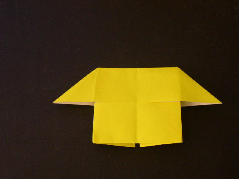
The second use-case we consider is a shopping app that launches when the device is folded into a shop shape [1]. The app will then allow the user to navigate through the products in the store, add items to their basket and pay.


The third use-case is as a game. The game we chose to demonstrate the idea is called Hungry Hippos. This is a 4-player game where each player does their best to get the most points. The device configuration we show below is what the actual game looks like. Therefore, we are using the flexible ability of our device to mimic the real world.


The fourth use-case we consider is when multiple apps map to the same device configuration. The examples we use are a web browser and a maps application. These will typically be in a rectangular shape. Therefore, when the device is in this configuration, the user is given a choice of whether they want to launch web browsing or maps. With both these applications though, the content is adjusted to fit the size of the display. This would be similar to Paddle [2,3].


[1] "Origami House", Origami Instructions, http://www.origami-instructions.com/origami-house.html
[2] Raf Ramakers, Johannes Schöning, Kris Luyten. "Paddle: Highly Deformable Mobile Devices with Physical Controls". In Proceedings of the SIGCHI Conference on Human Factors in Computing Systems (CHI '14).
[3] Raf Ramakers, "Paddle: Highly Deformable Mobile Devices with Physical Controls ", https://www.youtube.com/watch?v=zLe52PFZrtc

Week 4 of The Build: Part 1 - Paper Tracking & Projection

This week, we made big steps in tracking and projecting onto paper. We also started developing the use-cases that we will demonstrate. I'll start with paper tracking.


Paper tracking & projection:

After calibration, we use the Kinect and OpenCV to detect the paper. The contour functions of OpenCV are good for detecting the paper. To find contours, OpenCV defines a curve that joins all the continuous points along the boundary of an object that has the same colour or intensity [1]. To work best, there should be a big contrast between the object you want to detect and the background. Therefore, we bought a black cloth to put behind the white paper. When a threshold [2] is applied, there is a clear distinction between the paper and the background.

The contours found by OpenCV can be many. Therefore, we applied a contour approximation method to remove the redundant points on the contour. With the points of the contour and the Kinect depth information, we get coordinates for the paper in world space. With a set of transformations using the view matrix and projection matrix, the projector is then able to project onto the paper.


Below is a video demonstrating that we are able to track the paper and project onto it. To further develop this, we need to handle rotations as currently, the system doesn't handle the paper being rotated well.


[1] "Contours : Getting Started", OpenCV 3.0.0 Documentation, http://docs.opencv.org/trunk/doc/py_tutorials/py_imgproc/py_contours/py_contours_begin/py_contours_begin.html
[2] "Basic Thresholding Operations", OpenCV 2.4.9.0 Documentation, http://docs.opencv.org/doc/tutorials/imgproc/threshold/threshold.html

21 November 2014

Week 3 of The Build

Although we seemed to make good progress last week, the majority of our efforts this week involved having to reimplement a lot of what we had already done and thought we had completed.


We had calibration of the Kinect and projector completed last week but this did not incorporate the depth sensor values for the Kinect which was important to include. Our final calibration method is based on that used by some of the team in the BIG lab.


Above is our calibration in action. A checkerboard is projected and the Kinect recognises this checkerboard pattern. The difference with this calibration though is that we take 6 recordings for calibration instead of just the 1 we used last week. Each recording is with the checkerboard at a slightly different angle and orientation (shown below). This allows the calibration program to calculate the camera intrinsic and extrinsic parameters [1]. A projection matrix and view matrix are then calculated. These are what we feed into our Ogre application.


To improve calibration further, we turned the projector and Kinect to be the correct way up on our rig. This helped us to get a lower error for our calibrations. From talking to BIG researchers, we found that an error value of 2 or less is suitable. Our new rig configuration gives us error values in this range. Previously, our error was about 5 which was far too high.


References:

[1] Sagawa, R.; Yagi, Y., "Accurate calibration of intrinsic camera parameters by observing parallel light pairs," Robotics and Automation, 2008. ICRA 2008. IEEE International Conference on , vol., no., pp.1390,1397, 19-23 May 2008
doi: 10.1109/ROBOT.2008.4543397
URL: http://ieeexplore.ieee.org/stamp/stamp.jsp?tp=&arnumber=4543397&isnumber=4543169

20 November 2014

Pressages: Augmenting Phone Calls With Non-Verbal Messages


This week, we had a lecture from Eve Hoggan, co-author of "Pressages: Augmenting Phone Calls With Non-Verbal Messages" [1]. She discussed her research on ForcePhone which allows the sending of non-verbal messages by squeezing their phone. Vibration technology is mostly used purely for feedback. However, Eve and her team propose using vibrations to become part of the conversation itself.

A user study was conducted that showed how couples in long distance relationships could use Pressages to augment their communication. The conclusion was that augmenting communication in this way has value in expressing greetings, presence and emotions.

References:

[1] "Eve Hoggan, Craig Stewart, Laura Haverinen, Giulio Jacucci and Vuokko Lantz",Pressages: Augmenting Phone Calls With Non-Verbal Messages,"UIST '12, October 7-10 2012", ACM 2012

15 November 2014

Week 2 of The Build


This week we focused on building a rig to hold the Kinect and projector and continued to work on tracking the paper.

When building our rig, we knew it had to be able to support the weight of the Kinect and projector combined. In addition, the Kinect and the projector had to be aligned to make tracking easier. Initially, we felt that the Kinect and projector had to be perpendicular to the surface. Our initial rig allowed the Kinect and projector to be perpendicular to the surface (no picture available - we forgot to take a picture). However, this initial rig was not secure enough for our needs. Through talking to lab assistants and doing our own research, we found that we can have them at an angle and still be able to do the tracking and projection. With these constraints, we built the rig shown in the image above. As you can see we use a camera Tripod to hold the devices. The Tripod allows us to change the angle of projection and also the height.

Once we have completed tracking of the paper with the Kinect, we plan to use Ogre to project onto the paper. Ogre is an open source 3D Graphics Engine. Therefore, in order to project onto the paper, we will model the paper in a 3D scene and place a camera in our scene that matches the position of the physical Kinect and projector in the real world. This will allow us to map a texture onto the paper that will then be projected.

Before we can accurately track the paper, we need to calibrate the Kinect. A research paper from Microsoft Research [1] describes how to perform quick calibration using a Kinect. To summarise the research paper, a checkerboard is shown to the Kinect and a maximum likelihood framework is used to calibrate the camera. The checkerboard pattern is commonly used in colour camera calibration. Since we have a projector, we project the checkerboard through that instead of having a physical checkerboard for calibration.

The images below show the projection of the checkerboard pattern and how this pattern is fed into our Kinect software to calibrate the device.


References:

[1] "Zhang, Cha; Zhang, Zhengyou; ",Calibration between depth and color sensors for commodity depth cameras,"Multimedia and Expo (ICME), 2011 IEEE International Conference on",Pages 1-6,2011,IEEE


7 November 2014

The Start of Implementation


After completing a literature review the previous week, my group and I began getting to grips with implementing our interactive device.

To begin with, we felt there were two key parts to the project that we should start with.

The first is being able to recognise a sheet of paper through the Kinect camera and track the paper as it moves. This is what the sub-team, to the right in the image above, were working on. It took a lot of time to get the Kinect set up and get the programming environment set up. Also, we wish to use OpenCV to do tracking and this took time to get set up. By the end of the week, this sub-team were able to have a Kinect camera feed fed into an OpenCV program. Next week, we aim to complete the basic paper tracking.

The second key part is being able to project onto the paper given the coordinates of the paper that are provided from the first part above. With another team member, this is what I worked on. At the end of the week, we were able to project a shape through the picture with coordinates that we predefined.

Next week, we aim to project onto paper and automatically adjust the coordinates of our projection based on the actual position of the paper. This will involve having to combine both this part with the first part above. This will allow us to have a very basic application that tracks paper and projects onto it as the paper moves.